Prev Tutorial: Detection of ArUco Boards
Next Tutorial: Detection of Diamond Markers
ArUco markers and boards are very useful due to their fast detection and their versatility. However, one of the problems of ArUco markers is that the accuracy of their corner positions is not too high, even after applying subpixel refinement.
On the contrary, the corners of chessboard patterns can be refined more accurately since each corner is surrounded by two black squares. However, finding a chessboard pattern is not as versatile as finding an ArUco board: it has to be completely visible and occlusions are not permitted.
A ChArUco board tries to combine the benefits of these two approaches:
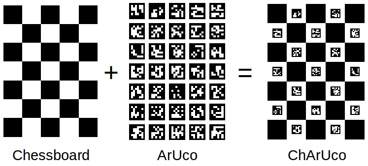
The ArUco part is used to interpolate the position of the chessboard corners, so that it has the versatility of marker boards, since it allows occlusions or partial views. Moreover, since the interpolated corners belong to a chessboard, they are very accurate in terms of subpixel accuracy.
When high precision is necessary, such as in camera calibration, Charuco boards are a better option than standard Aruco boards.
Goal
In this tutorial you will learn:
- How to create a charuco board ?
- How to detect the charuco corners without performing camera calibration ?
- How to detect the charuco corners with camera calibration and pose estimation ?
Source code
You can find this code in opencv_contrib/modules/aruco/samples/tutorial_charuco_create_detect.cpp
Here's a sample code of how to achieve all the stuff enumerated at the goal list.
ChArUco Board Creation
The aruco module provides the cv::aruco::CharucoBoard class that represents a Charuco Board and which inherits from the Board class.
This class, as the rest of ChArUco functionalities, are defined in:
To define a CharucoBoard, it is necessary:
- Number of chessboard squares in X direction.
- Number of chessboard squares in Y direction.
- Length of square side.
- Length of marker side.
- The dictionary of the markers.
- Ids of all the markers.
As for the GridBoard objects, the aruco module provides a function to create CharucoBoards easily. This function is the static function cv::aruco::CharucoBoard::create() :
- The first and second parameters are the number of squares in X and Y direction respectively.
- The third and fourth parameters are the length of the squares and the markers respectively. They can be provided in any unit, having in mind that the estimated pose for this board would be measured in the same units (usually meters are used).
- Finally, the dictionary of the markers is provided.
The ids of each of the markers are assigned by default in ascending order and starting on 0, like in GridBoard::create(). This can be easily customized by accessing to the ids vector through board.ids, like in the Board parent class.
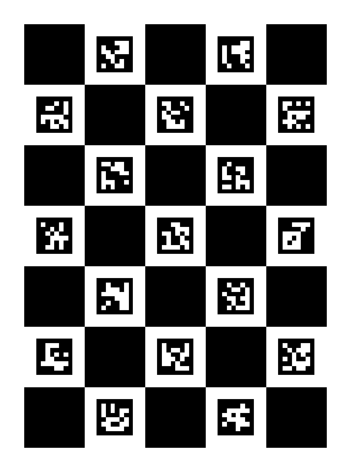
Once we have our CharucoBoard object, we can create an image to print it. This can be done with the CharucoBoard::generateImage() method:
- The first parameter is the size of the output image in pixels. In this case 600x500 pixels. If this is not proportional to the board dimensions, it will be centered on the image.
boardImage: the output image with the board.- The third parameter is the (optional) margin in pixels, so none of the markers are touching the image border. In this case the margin is 10.
- Finally, the size of the marker border, similarly to
generateImageMarker()function. The default value is 1.
The output image will be something like this:
A full working example is included in the create_board_charuco.cpp inside the modules/aruco/samples/.
Note: The create_board_charuco.cpp now take input via commandline via the OpenCV Commandline Parser. For this file the example parameters will look like
ChArUco Board Detection
When you detect a ChArUco board, what you are actually detecting is each of the chessboard corners of the board.
Each corner on a ChArUco board has a unique identifier (id) assigned. These ids go from 0 to the total number of corners in the board. The steps of charuco board detection can be broken down to the following steps:
- Taking input Image
The original image where the markers are to be detected. The image is necessary to perform subpixel refinement in the ChArUco corners.
- Reading the camera calibration Parameters(only for detection with camera calibration)
The parameters of readCameraParameters are:
- filename- This is the path to caliberation.txt file which is the output file generated by calibrate_camera_charuco.cpp
- cameraMatrix and distCoeffs- the optional camera calibration parameters
This function takes these parameters as input and returns a boolean value of whether the camera calibration parameters are valid or not. For detection of corners without calibration, this step is not required.
- Detecting the markers
The parameters of detectMarkers are:
- image - Input image.
- dictionary - Pointer to the Dictionary/Set of Markers that will be searched.
- markerCorners - vector of detected marker corners.
- markerIds - vector of identifiers of the detected markers
- params - marker detection parameters The detection of the ChArUco corners is based on the previous detected markers. So that, first markers are detected, and then ChArUco corners are interpolated from markers.
- Interpolation of charuco corners from markers
For detection with calibration
For detection without calibration
The function that detect the ChArUco corners is cv::aruco::interpolateCornersCharuco(). This function returns the number of Charuco corners interpolated.
std::vector<cv::Point2f> charucoCorners: list of image positions of the detected corners.std::vector<int> charucoIds: ids for each of the detected corners incharucoCorners.
If calibration parameters are provided, the ChArUco corners are interpolated by, first, estimating a rough pose from the ArUco markers and, then, reprojecting the ChArUco corners back to the image.
On the other hand, if calibration parameters are not provided, the ChArUco corners are interpolated by calculating the corresponding homography between the ChArUco plane and the ChArUco image projection.
The main problem of using homography is that the interpolation is more sensible to image distortion. Actually, the homography is only performed using the closest markers of each ChArUco corner to reduce the effect of distortion.
When detecting markers for ChArUco boards, and specially when using homography, it is recommended to disable the corner refinement of markers. The reason of this is that, due to the proximity of the chessboard squares, the subpixel process can produce important deviations in the corner positions and these deviations are propagated to the ChArUco corner interpolation, producing poor results.
Furthermore, only those corners whose two surrounding markers have be found are returned. If any of the two surrounding markers has not been detected, this usually means that there is some occlusion or the image quality is not good in that zone. In any case, it is preferable not to consider that corner, since what we want is to be sure that the interpolated ChArUco corners are very accurate.
After the ChArUco corners have been interpolated, a subpixel refinement is performed.
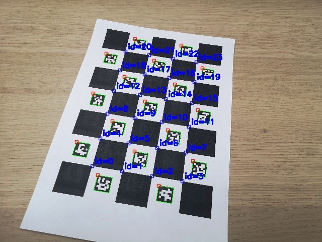
Once we have interpolated the ChArUco corners, we would probably want to draw them to see if their detections are correct. This can be easily done using the drawDetectedCornersCharuco() function:
imageCopyis the image where the corners will be drawn (it will normally be the same image where the corners were detected).- The
outputImagewill be a clone ofinputImagewith the corners drawn. charucoCornersandcharucoIdsare the detected Charuco corners from theinterpolateCornersCharuco()function.- Finally, the last parameter is the (optional) color we want to draw the corners with, of type
cv::Scalar.
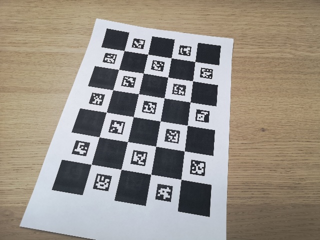
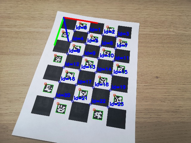
For this image:
The result will be:
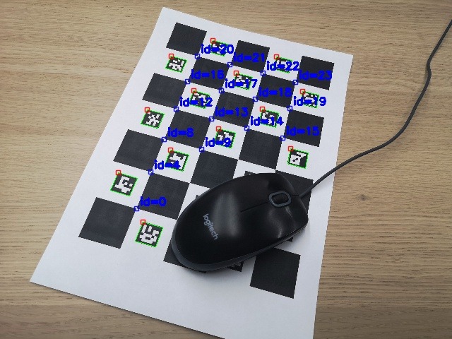
In the presence of occlusion. like in the following image, although some corners are clearly visible, not all their surrounding markers have been detected due occlusion and, thus, they are not interpolated:
Finally, this is a full example of ChArUco detection (without using calibration parameters):
Sample video:
A full working example is included in the detect_board_charuco.cpp inside the modules/aruco/samples/.
Note: The samples now take input via commandline via the OpenCV Commandline Parser. For this file the example parameters will look like
ChArUco Pose Estimation
The final goal of the ChArUco boards is finding corners very accurately for a high precision calibration or pose estimation.
The aruco module provides a function to perform ChArUco pose estimation easily. As in the GridBoard, the coordinate system of the CharucoBoard is placed in the board plane with the Z axis pointing out, and centered in the bottom left corner of the board.
The function for pose estimation is estimatePoseCharucoBoard():
- The
charucoCornersandcharucoIdsparameters are the detected charuco corners from theinterpolateCornersCharuco()function. - The third parameter is the
CharucoBoardobject. - The
cameraMatrixanddistCoeffsare the camera calibration parameters which are necessary for pose estimation. - Finally, the
rvecandtvecparameters are the output pose of the Charuco Board. - The function returns true if the pose was correctly estimated and false otherwise. The main reason of failing is that there are not enough corners for pose estimation or they are in the same line.
The axis can be drawn using drawFrameAxes() to check the pose is correctly estimated. The result would be: (X:red, Y:green, Z:blue)
A full example of ChArUco detection with pose estimation:
A full working example is included in the detect_board_charuco.cpp inside the modules/aruco/samples/detect_board_charuco.cpp.
Note: The samples now take input via commandline via the OpenCV Commandline Parser. For this file the example parameters will look like
